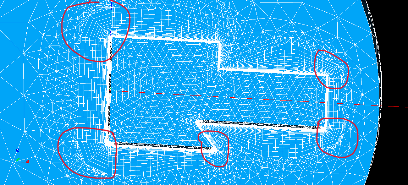
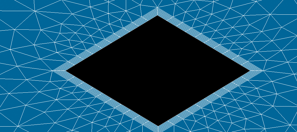
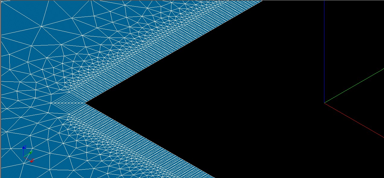
I have been working on Salome with this geometry in order to test the behaviour of viscous layer creation on sharp corners. The issue I am having is that the transition on these corners is simply too abrupt, as can be seen in the following image:
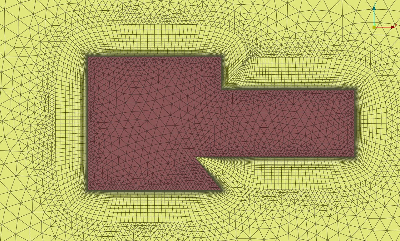
The mesh I am generating on Salome is then being compared to ANSA, and I am trying to find a way in which I can make the corner transition smoother. In ANSA, this fucntion is called “Smooth normal vectors”, but I cannot seem to find anything in Salome that does the same. Does anyone know of a workaround?
Hey, thanks for your reply. I tried the other methods but they give me the same result. I am mainly interested in the node offset, as it works better for my specific application. The parameters I used are the following:
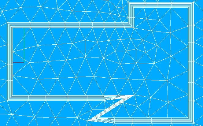
I have the same problem. I try to create a 2D psedo mesh for OpenFOAM (3D mesh with only one cell in the z direction). So, I first create a 2D mesh and then extrude it at one cell on the z direction.
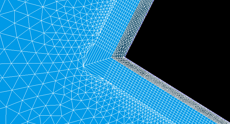
However, when I use Viscous layer, I have a similar problem with gcayser (see screenshot below).
I used step file from Rhino to import the geometry and I grouped the four edges of the square in Geometry section.
I think the solution is somehow to “group” the four edges.
Further more, I would like to ask, is python with salome worth giving a try?
clearly.
sadly in my current PC I can not use salome as I am having issues with. will check later, but run the pyhon script to check what I did. and guide you from that
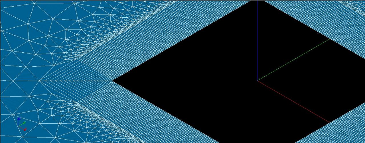
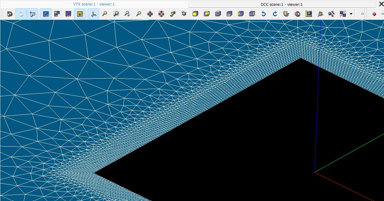
I have examined your file and tried to follow the steps you took for the generation. However, beacause I need higher resolution on near wall edges, I increased the number of segments on edges through python. This resulted to the undesired result on the vertices (see image below).
I also atatch the .py file, which only differes in th number of segments (you used 10, I used 100)
can confirm that thats not the expected behavior…
I also tried to hackish solve it by doing a 3D mesh, (as the BL addition in 3D has some extra possibilities that the 2D does not have) but same result.
Sure. I got inspiration from you. You helped a person on solid/fluid hybrid meshing. There, first you partition the geometry. Then, create a mesh container to include sub-mesh volumes. The role of that container is to connect those volumes through interfaces. How do we get those interfaces? There are several methods: e.g., Partitioning in Salome, Boolean Fragments in FreeCAD.
Why did I follow this way? I noticed that the edge offset is going up vertically. I created our desired offset manually. The rest is as explained above. If desired, ‘equidistant’ BL layer distribution can be replaced by a distribution function as in multi-block-structured hexa meshing.
It is obvious that VL routine did not behave as expected. What I did was to construct a solution using fundamental tools that can help enthusiasts develop their own method. Although creating offset edges seems to be a long way, indeed they are just point clouds that one can use them to write a custom offset technique in order to solve this issue entirely.
No issues with it buddy. Actually as you said you followed my recommendations in another post. I was curious as my knowledge in smesh is way more limited than in geom itself so I was thinking that there was something I was missing that’s why I was asking as your previous comment wasn’t clear to understand that you were adding extra sections of faces just for the vl.