Hello. I am having a problem in the Salome 9.9.0 When I try to use Projection 2D to make the meshes of the opposite surfaces the same so that I can later apply periodic or cyclic boundary conditions, I get the following error that says the corresponding surfaces do not have the same shape, even though they are completely the same.
unexpected geometry : topology of source and target faces seems different*
Can you display the vertexes of each face ? I think you might have extra vertexes in one over the other face. I have faced that issue already.
If it is not that, how are you getting the 1d discretization of your faces?
Thank you for your response.
Yes, you are absolutely right. It seems that one of the faces has extra vertices.
Do you know why this happened?
I also used wire discretisation for the 1D mesh.
if you have different vertices, you will not be able to use projection. they need to be exactly the same, vertex by vertex edge by edge etc.
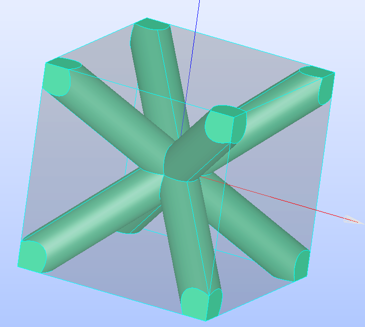
it seems as you create the faces from intersection with cylinders or cylindrical faces (next time you post for asking for help try to give more detail of the issue ). the seam of the cylinders might have been in different positions (seam= straight edge of the cylinder) which generates the extra vertex. if that is the case, as you have only a partial intersection try rotating them till the seams do not intersect the face this will generate a face with less vertexes and that (if you are right that are equal) that is geometrically equal.
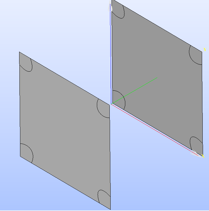
Thank you for your answer. You guessed the problem correctly to some extent, but the problem is, as you can see from the figure below, it is not possible to remove the seam of the cylinders by rotation. Therefore, what I did was to try to change the seams of the cylinders so that they fall on the vertices of the cube or if it gives an extra vertex, it also gives that vertex symmetrically on the opposite surface.
With this, now fortunately I can match the mesh of the two opposite surfaces with Projection and this shows that I have been able to completely match all the opposite surfaces. But the problem that exists now and is very strange is that I can project each of the two opposite surfaces separately, but I cannot do them all together. In other words, after I match the mesh of 4 opposite surfaces, for the last two surfaces, it gives the same error as before and says that the topologies of the surfaces are not the same, while they are completely the same, even in terms of vertices and so on.
lol… periodic open cell strucutres… it remembers me of my thesis… ah lala… it is normal you geometries are still different. you can see it in the image that you post it.
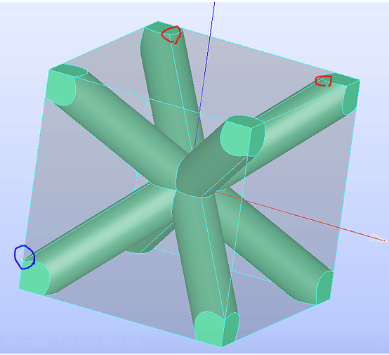
try fixing all the seams so they go to the vertex of the “1/4” of circle you get from the intersection. as is the case for the blue one. and not the red ones that they give you extra vertexes on the surface. if you do all like the blue one, you should in principle get only 12 vertexes for each face. and they will be all geometrically equal.
best regards, and good luck
Thank you very much for your helpful advice. I followed your instructions exactly, and I no longer have the problem of unequal vertices in the opposite surfaces and Projection works well for any two opposite surfaces.
However, the problem I am facing is no longer that I cannot project opposite surfaces, but a more complicated one. For example, after projecting the two surfaces in the direction of the x-axis, when I go to the two surfaces in the direction of the y-axis, I get an error that the topologies are not identical. However, if I start from the two surfaces in the direction of the y-axis, I get the same error for the x-axis surfaces.
In other words, it seems that the geometry of the other two surfaces has changed by projecting the meshes of two surfaces of the cube, but when I check, I see that it has not changed. BCCUCFGnew.hdf (382.0 KB)
Do you understand my new problem? Do you have any ideas for this?
Test define all edges to one 1d submesh. Eg wire discretization with 10 elements. And then the 2d projecyion alone. If that does not work I am not sure another way around. Sorry
Ok I succesfully mesh the geometry with the 3 projections. the main issue is in the projection/2D surface mesh, you should do it face by face which is quite annoying but clearly doable. here you can find the 3D tet mesh with xmin equal to xmax, ymin equal to ymax and zmin equal to zmax. up to my knowledge of salome, I don’t know if it is possible to get exactly the same surface mesh for all the cube faces might be possible with the hypothesis import 1D-2D elements… but I don’t have knowledge of how exactly woks. but if that is the case the logic would be to mesh the 1D edges of one side, surface mesh separately for each face inside that side, and then import for the corresponding faces. you could even create only 1 of the small faces and import it to all other faces even the small ones in the same side. have a look in the hdf file I am uploading. up to here is where I can go with my knowledge but for an AMI simulation should be already perfect (outside of the tetra nature of the mesh.)
best regards, BCCUCFGnew.hdf (3,4 MB)
EDIT: correction you can use project 2D with all similar faces, which creates a perfect homogeneous mesh. (way cleanner) BCCUCFGnew.hdf (1,3 MB)