I need to mesh a building floor containing beams and columns.
I’ve imported the geometry in igs format. It contains surfaces, lines and points.
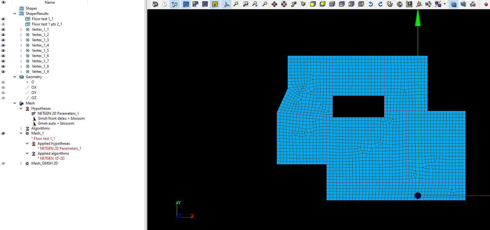
I’m using NETGEN 1D-2D algorithm to generate a quasi quad mesh. After playing with the parameters I get a mesh close to what I need. The main problem is I need the mesh to include the column points, and I haven’t managed to do so (see image below).
I’ve tried to group the vertices in the shaper module but I don’t really know how to use them.
from what I know, you can not for a mesh in salome to pass thought a specific point in a surface. (I have never used 0D meshes/submeshes if i were you i would have a look on that might be helpful).
that being said, you can do this by modification of the mesh using python. detecting the node that has the position closer to the point/vertex you want, and then use move node to move it to the correct position.
it takes around 15 lines of code in python to find the closest vertex to a point location and move it. salome was not necessarilly thought for that kind of simulations so not necessary has the build in tool.
Sounds like a very simple thing to do indeed. I don’t mind adding the 0D elements manually this time.
I’ve grouped the points ans surfaces separately but I don’t know how to add the geometry, apply hypothesis and run algorithm to two different geometries together, in my case surfaces and points. Floor test grouping points.hdf (462.6 KB)
What I’d do to simulate columns is using 1D elements which share the same nodes with the shell. Then in mesh module simply choose wire discretization for beams. I’d suggest placing them in geometry group called for example “1D” and add submesh only to that group. One element per length should be ok for supporting the plate/floor.
In this case you’ll have very high stress in those shared nodes. If you’d like to simulate shape of the support I’d cut the surface around the node with the exact cross-section shape of the supporting beam and add a glued/tied contact in study in a way the solver you’re using requires.
But If you’d like to use only nodes, you don’t have to use anything else than you’ve got in your Mesh_1. If you look at groups you will find nodal group containing your nodes where the columns are supporting.
One more thing, if I’d like to add BC to those points where the columns are I’d cut the surface with horizontal and vertical lines in a way so that the cutting lines would intersect where the columns’ nodes are. Then I’d add geometrical group containing only vertices in the intersections then I’d have all I need to have a mesh group for applying BCs. This is the simplest way and you don’t have to have 0D elements.
In my previous post I’ve written that you have already all in the mesh, but I was wrong. I thought that points you created in geom module share the same nodes with shell. After looking again I saw they don’t share the same location.