Hello,
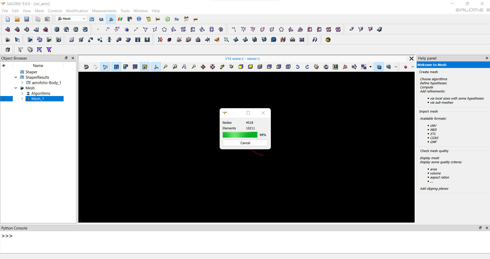
I made a geometry with a NACA0012 airfoil, but I can’t mesh it, when I compute the mesh, it loads until 98% and then stops. I already made some others meshs, so I think that’s a problem with the geometry. I tried others meshs but all stops at 98%.
In the following .hdf file, it’s just a default mesh and the .step file, the geometry.
There is no problem outside that the complete bar is not representative… Actually the meshing is been done correctly it is only that it is taking a lot of time. If you wait more it will complete. In my experience with all big meshes it always fill up until 98% and then it stops there… And that 2% could be way more than all the rest of the process. But in any case you simply need to wait more to get the mesh. Nevertheless it might be some issues that the meshing algo is having trouble with (and that’s way it takes too much time)
Try by changing the element size to make it faster and then reduce the size little by little to achieve the desired refiment. Notice that only the gmesh hxt (I am not over the computer so it might be something similar the correct name) is the only parallel meshing algo in 3d.
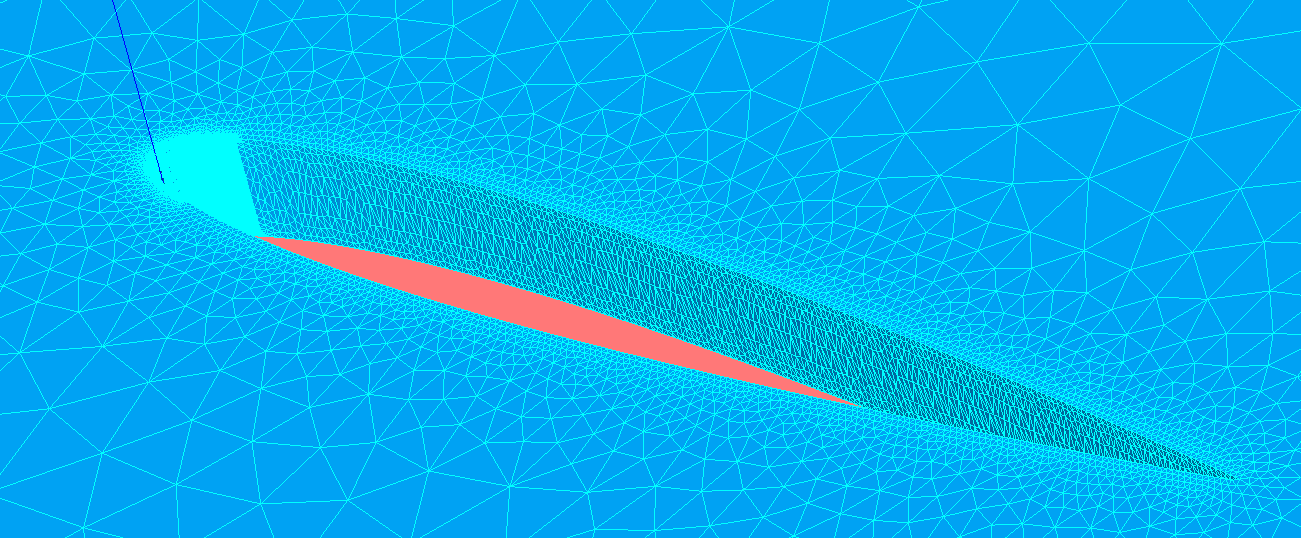
in my first message, I answered from common experience I had had in the past for large meshes. after having a look at the screenshot from christophe, your issue is in the way you generated your geometry. to be more specified in the wall section that is composed of several small edges for each side. I would recommend to improve the quality of your geometry, nevertheless, if you want to work with this geometry you can ‘trick’ salome to achieve somewhat, a ‘good’ mesh. for this, you need to do the following workflow:
create a group of edges for each side of edges that are in wall and placed in each side of the faces group.
create your mesh, without computing it.
create a submesh for the group created in the first step with the 1D wire discretization and define a number of elements (for example in the following screenshot you have it for 1 element only which is the minimum, and as you can see in the screenshot it is already really refined as this will define one element for ‘each’ edge that is inside of each group.)
here you have the salome file with the workflow I mentioned. (nevertheless, I insist on getting rid of these problematic faces, I mean rework the geometry) sal_aero2.hdf (611,0 KB)
the file I uploaded is a .7z file that I change the format to be able to upload it to the forum. (you will need to change it back to 7z and then extract it to recover the salome hdf file
best regards.
Hello,
here you will find a correct case from the input data I got from the original hdf file and step file.
keep in mind that it is an approximation as the data points I got them by inspecting the step file. nevertheless, it should do the work.
I hope that by looking at the hdf file you will understand better the issue between your approach and the correct one.
just for info, with the correct approach, the meshing with netgen 1D-2D takes less than a second. repearedCase.hdf (745,2 KB) @cbourcier I would appreciate if you could throw an insight in a correct approach to “repear” the geometry from the step file. in the hdf file i upload, it involved scripting and recovering point coordinates, but geometry module should have more than enought tools to solve this type of issues, could you mention how you would do/approach it? as I am interested for more complex cases that would not be possible to recover the points and re do entirely the geometry.
F.
Fusing edges of C0 continuity is done by OCCT’s function ConcatenateWireC0, but it is not directly available in GEOM or SHAPER. It is called in Filling to create a face by several edges or wires.
So, in wing_repaired_by_filling.hdf (596,0 Ko), I extracted the wires from the wing and called filling. But the result is not smooth. So I extracted the bottom edge, create the bottom face with the external wire, and extrude it to get the repaired shape.
In SHAPER, wireToEdge from GeomAlgoAPI_ShapeTools calls ConcatenateWireC0. So it could be used to create a feature doing the job.