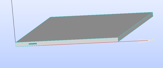
This is a cooling plate with a coolant flow channel inside. The square hole on the left is the coolant inlet. When I use “New Entity/group/create Groups” to create a group named inlet and then create a mesh, I can only define the entire plane where the square hole is located as the coolant inlet. How can I define only the square hole as the coolant inlet?
Hello
did you ask the right question? Have a look at the Doc of your FEM solver.
As far as I remember, 2 bodies must be defined. Body 1 for the fluid and body 2 for the metal plate. Each body has its own surfaces. These are assigned boundary conditions in the FEM program.
with best regards
I have solved the Problem.The Method is wie your Suggestion.Thank you for your help.
@schoko hello , can you share how did solve the problem ?
I’ve created a geometry with multiple inlets. For each inlet, I started by creating a surface (either a disk or a rectangle), then translated it to the target region. Afterward, I added a thickness to the surface and cut the main box using this thickness to create the inlet or outlet. So far, everything seemed to work fine.
The issue arose when I started organizing the geometry into groups for CFD simulation. While creating groups for walls and floors was straightforward, I ran into trouble with inlets and outlets. Specifically:
- I couldn’t select the inlet to include it in a group.
- To address this, I tried fusing or exploding the inlet to separate it from the wall surface. This allowed me to create a group, but the group only appeared under the inlet’s branch in the tree, not under the main box’s branch.
- If I tried to create a group under the box’s branch, I encountered an error, as if the inlet wasn’t properly “attached” to the box.
So my questions are:
- Is there an alternative method for creating inlets and outlets in Salome?
- If this is the correct approach, what might I be doing wrong?
Thank you so much for your help! ![]()
