I am looking for a way to create this geometry in SALOME. my issue is in the meshing part of it.
I would appreciate if anyone could help me.
I am looking for a way to create this geometry in SALOME. my issue is in the meshing part of it.
I would appreciate if anyone could help me.
here
cyl.hdf (119,1 KB)
Thank you very much ![]()
I have some questions and it would be your kindness to answer them
First why we used that Plane_1
and the second is i couldn’t find Hexahedron in mesh section. but when i loaded your file it now is available. is that also the result of that plane as well or not?
you need to decompose your geometry into blocks, ie., block= a body of 6 faces, 12 edges, 8 vertexes. all of them should share the internal faces so you dont get double nodes in the internal faces (for this if you import a geomety from another cad, use repair/glue faces on the compound). the plane is to transform the two concentric difference of the cylinders (6 edges, 4 faces,4 vertexes) to two blocks each of them being a ‘C’ like geometry which each one having the elements i mentionned previously.
for hexahedron not being shown, is because you are trying to create a mesh in a body that can not be meshed with that algorithm, salome detects this so it does not allow you to use it. create a simple cube, and re try and you will see that it shows.
regards
Thank you for your kind response. I truly appreciate it and understand everything clearly. Wishing you all the best in life—good luck!
Sorry to bother you again
I wonder how can i change the number of segments along radial direction, axial direction, and theta direction?
you use different 1D submeshes with for the corresponding edges of each propagation group,
for example for a simple cube, you would have 3 different propagation groups, X,Y,Z then you can create a submesh with number of elements for the 4 edges in X, 4 in Y and 4 in z (by constructing a group of the corresponding edges and applying the sub mesh to that group)
Thank you very much — I got it and tested it, and it works perfectly. My next question is: I managed to create separate meshes for the Z and θ directions, while leaving the R direction at its default setting.
For the Z direction, I used vertical lines as edges, and for θ, I used cylindrical curves.
Now, I’m wondering — if I want to define a custom mesh for the R direction as well, what kind of edges should I use?
I think i should use that edges along the plane right?
not sure I understand you correctly,
for Z you use the edges that goes in the direction of the axis
for theta you use the semi circles
for R you use the other edges (the ones going in/out for external to internal circles)
in a structured mesh is ALWAYS the same. you have i,j and k directions, you simply need to think of each block as a cube (streach compress the geometry in your head) and you will realize how it works
Thank you very much.
I got it. BTW, i meant for radial direction in cylinder, i use the lines (i have to define some in gemetry and then merge them into final partition) which are in fact the intersections of the plane with whole cylinder.
as I mentioned before:
the plane is to transform the two concentric difference of the cylinders (6 edges, 4 faces,4 vertexes) to two blocks each of them being a ‘C’ like geometry which each one having the elements i mentionned previously.
thats the reason of the plane having the other edges.
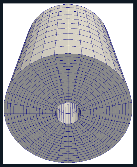
Sorry to bother you again, i wonder how can i do the same thing to a solid cylinder? i mean with no cut involved.
Lol, you can not. It you could Salome would be at level of the most expensive meshing softwares around. You need to decompose your geometry into blocks for structured meshing. In Salome the most near would be body fitting algorithm for unstructured hex dominant mesh.
Thank you. I used try and error which finally i managed to find how can i do it on solid cylinder. this is the result i got
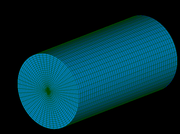
okey, i thought that you wanted something like an o grid , my bad.
That is wonderful that you found a solution. Can you share the method?