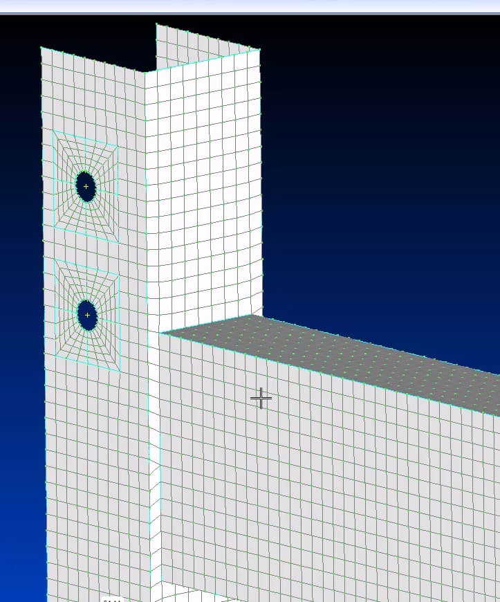
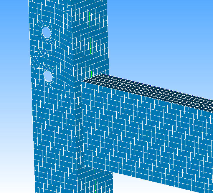
I’m trying to get a nice coherent quad mesh between 2 separate shell models, but the nodes dont seem to align, no matter what i do. The model was created in a CAD software as surfaces, then imported into SALOME as a .step file. Running a quick-and-dirty Netgen 2D-1D with max of 5mm and min of 3mm.
I’ve spend the last 3 hours reading up on the docs, and watching videos on youtube, but i’m unable to get anything better. I’ve tried creating a sub-mesh with similar parameters, but then for the 1D algorithm setting the “Propagation of node distribution on opposite edges”, for the vertical beam.
I have had success with mapped hex meshing on solids before, by dividing faces with the partition feature, but for some reason i cant seem to use many of the features in the SHAPER module for my shell.
So…
How would you recommend i approach this problem to get the above mesh?
hello, you file is empty, so not much people can help you with.
in any case, the workflow for a conformal mesh between two objects is the following (in geometry module):
create a compound of the different geometries you want to mesh, in you case your 2 shells.
define the different discretization groups you will use (in the compound object)
create a mesh to the compound and submeshes for each of the bodies and groups you made, this can be 3D, 2D, 1D or several together.
in case that you use algos from gmsh, this workflow is not so straight foward, (and I can not confirm that it is doable as i am trying to do that exactly).
best regards.
I prefer to use the shaper module, but i guess creating a compound is possible there too. Right?
Would that mean, say, creating a separate group for the faces around the holes? I’m not entirely sure what this would look like in practice. Drawing a rectange around the holes, extrude the sketch as a line extrusion, then use the partition command with the extrusion as the tool?
If i understand you correct: 1 big mesh operation for the compound (both of the shell parts). Then “below” this main mesh create 1 separate submesh for each of the 2 shell parts. Then, to do any part-specific refinement, as many submeshes for each area of refinement (defined as groups in the shaper module?) as needed. Correct?
I come from some proprietary software with the option to manually manipulate the meshes too. It seems to me like SALOME relies heavily on the use of a “change the algorithm/hypothesis + compute” workflow, rather than a “point-and-click refinement” kind-of workflow (FEMAP meshing toolbox comes to mind). Am i missing something here?
I also have a hard time finding proper learning material. Most of the videos on youtube rely on the geometry module, which i would like to avoid, and very few videos focus on anything beyond very simple stuff. I’m reading through the docs, but it’s a slow process. How would you recommend learning advanced use?
I prefer to use the shaper module, but i guess creating a compound is possible there too. Right?
yes you can, there are issues between shaper and mesh interconnection if you change to many times the shaper result, see the releases notes issues. in any case,personally i would recommend and say that they are complementary shaper and geom.
Would that mean, say, creating a separate group for the faces around the holes? I’m not entirely sure what this would look like in practice. Drawing a rectange around the holes, extrude the sketch as a line extrusion, then use the partition command with the extrusion as the tool?
depends on what you are looking for, if you want a hexa structured mesh like the one in the first image (not salome), you need to make the cutting of your geometry, as for example the o-grid like square around your cicle. then you would need to cut it in several places to ensure the conformity of the mesh.
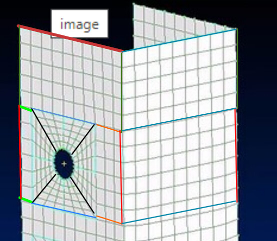
something like this in terms of group of edges. (for example) then you define for each group of edges of different colours, what are the number of elements (1D) so for exxample the dark red has equal number as the light green +blue+orange. etc. so it is conformal.
If i understand you correct: 1 big mesh operation for the compound (both of the shell parts). Then “below” this main mesh create 1 separate submesh for each of the 2 shell parts. Then, to do any part-specific refinement, as many submeshes for each area of refinement (defined as groups in the shaper module?) as needed. Correct?
yes more or less, you create a mesh (that includes everything) and you will ‘overwrite’ part of it (or specify part of it) with the submeshes.
there is not a lot of learning material. the only two for this type of work i know are this (one in french) https://www.youtube.com/watch?v=Fh3o5M_O1dc https://www.youtube.com/watch?v=kUpffiN9eVY
but they are really simple, and do not target everything. the learning is a lot of trying and error, reading other forum posts (you also have the old forum https://old.salome-platform.org/forum and reading the docs.
best regards
Thank you a lot for your time. As a side note - i must have messed up the file upload. I’ve edited the file, so now the google drive link contains my .hdf file. Feel free to take a look at it and let me know what you think, or give additional pointers/directions.
It’s a shame that the best way to learn is “trial and error”, because I feel that the approach in SALOME is quite different from anything else, so this approach is going to take a very long time. Lots of other people must have the same issues. Unfortunately, i dont speak french.
I’m going to have to give it another try soon. Thank you for great pictures, with drawings. I will return to this post once i (no doubt) run into issues again.