Hello, is it anyhow possible to exclude a shared faces from a partition instead of modelling a small gap between parts to have a disconnected mesh?
Thanks
Hello, is it anyhow possible to exclude a shared faces from a partition instead of modelling a small gap between parts to have a disconnected mesh?
Thanks
not sure If i understand correctly (as you have not give a lot of explenation, when asking for help try to give all the details you can even some sketchs by hand would help this makes easy to understand for others and to help you)
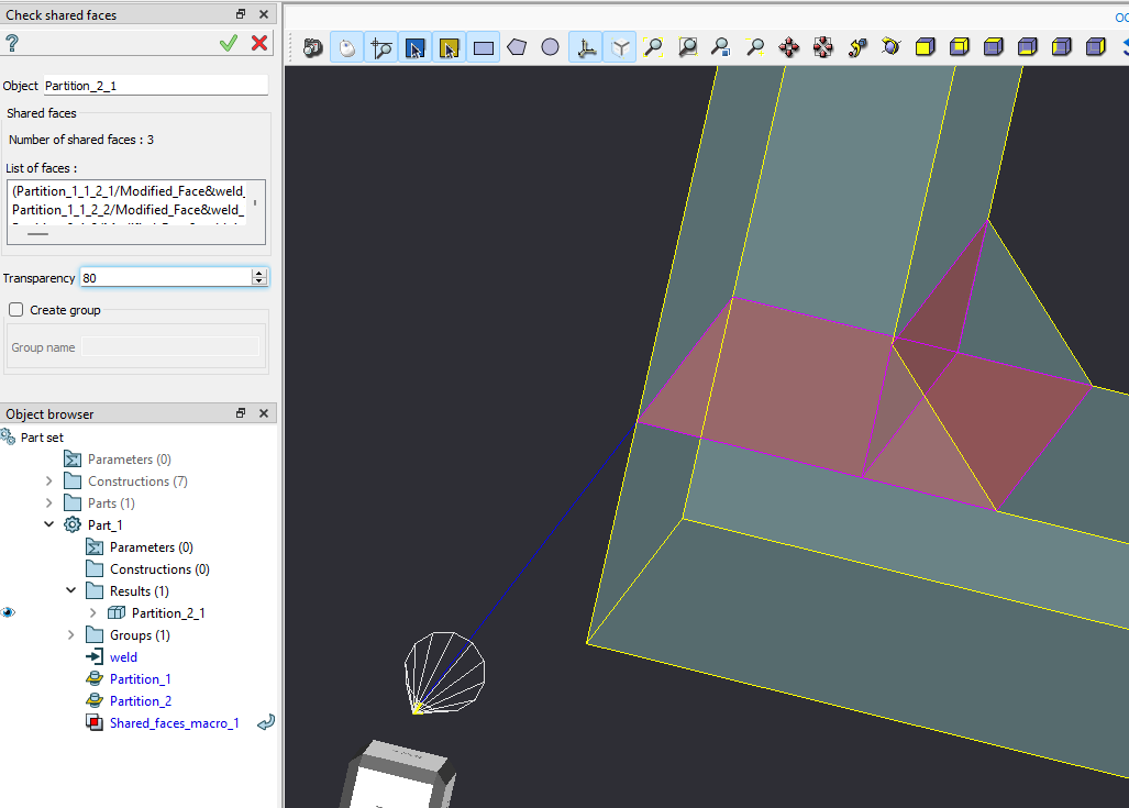
I think what you are looking for is repair/remove internal faces (you should use glue faces before) this will remove internal faces of a compound.
regards
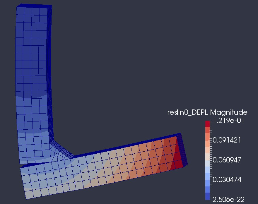
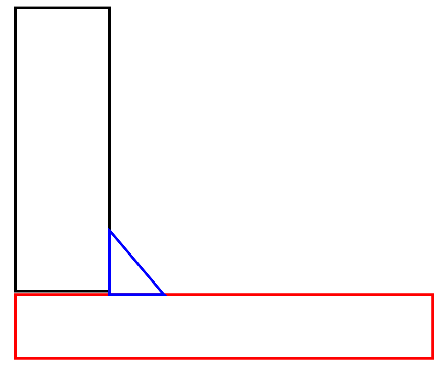
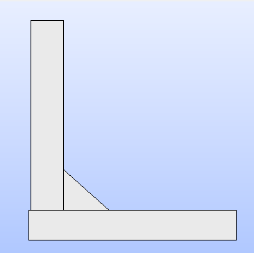
for example this. If I use partition for both plates and weld, it will be all connected. But I want to connect the plates only by the weld.
that your geometry looks like this at the end?
the workflow works IF there is a slight difference in the overlapping. for example like this:
the issue is that when you do it with the perfect connection, the remining faces after the partition will be exactly the same in the two sides, so the glue face tool will remove one.
with the modified geometry it works like charm. If you want to still use the perfectly aligned you need to use the second option of the glue face tool where you can select the faces you want to glue exactly and not glue everything you can version.
here is a .hdf example (with slight modification of the face):
exampleGlueFaces.hdf (193,4 KB)
Thank for help, but I still don’t quite get it.
However, the geometry has to be perfect (weld can be on both sides) and using Shaper module (because there, the geometry can be changed)
If I try to use partition first only for weld+plate1 and then weld+plate2 it always creates 1 partition where everything is shared.
in the example I gave you I beging from a imported geometry, you can simply use export to geom tool in shaper. I disagree with the ‘has to be perfect’ as you could give a highly small difference (0.0001) and will solve it. in any case. you can do it by scripting shaper creation of each block-> imporation to geom → glue intersect blablabla → mesh
shaper is limited in the number of tools for reparation and this kind of things I am not sure that it can glue only some faces only. but I am not familiar with shaper module can not help with that.
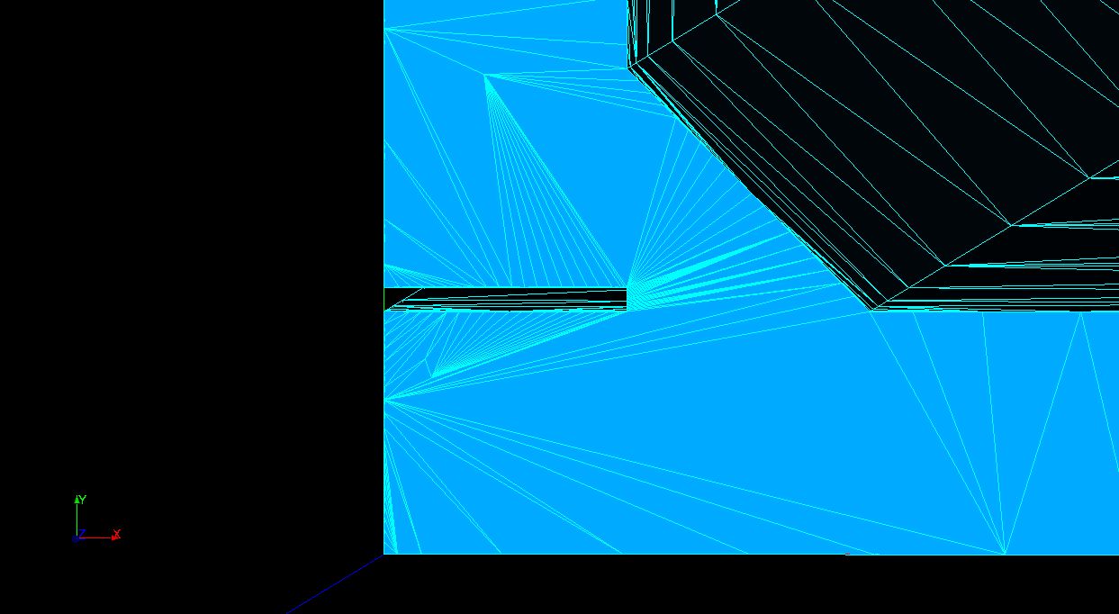
To have these small imperfections like 0.01 mm causes creation of very small and bad elements
Hallo
Why so complicated? Draw gaps where there is no connection between the plates and the weld seam. I don’t want to comment on the cross-linking in the area of these gaps. I have too little experience for that.
Yours sincerely
Luve
Hi,
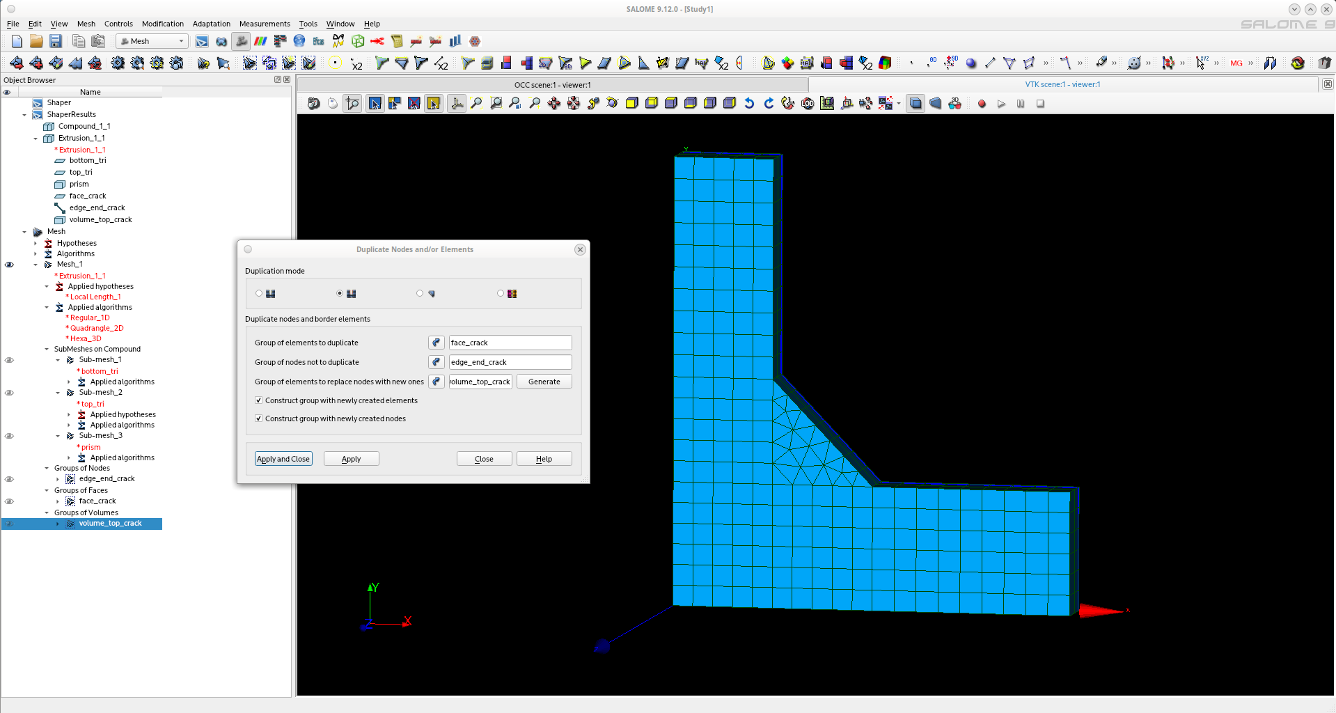
to make crack simulation, we usually double nodes in mesh to get better control than in CAD.
To do this, go to the menu Modification> Transformation> Duplicate Nodes and/or Elements. Select:
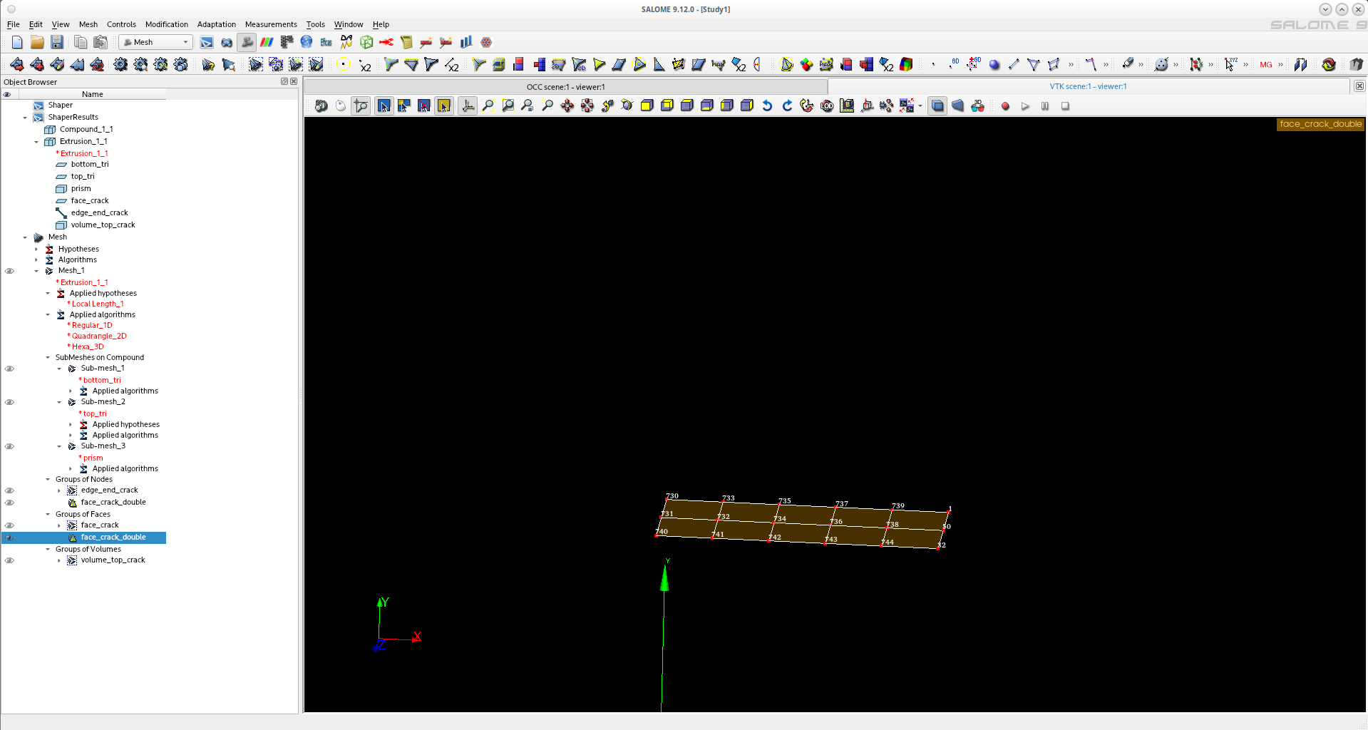
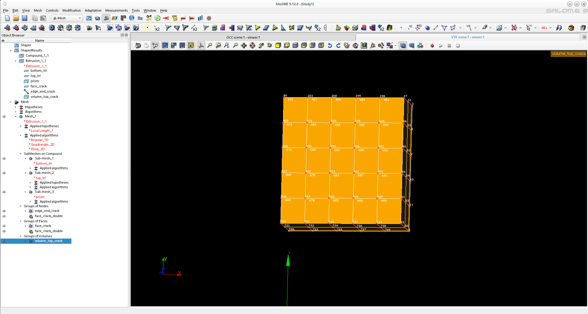
You can check by displaying the nodes numbers that the new nodes have been well affected to the volume elements, and that no double nodes are applied on the crack tip.
Have a look at the study and python dump.
Study1.hdf (85,9 Ko)
dump_duplicate_nodes.py (7,9 Ko)
Christophe
Hello,
I know already how to have disconnected nodes. I do it by creating mesh for 2 parts separately and projecting mesh of one face to another, then merge only the face nodes (which is simpler way than creating duble faces).
But I am looking on a way how to do it on geometry lever, to facilitate work when a geometry is complicated with many welds.
I have explained in this post ‘the second option’ how to achieve what you are looking for.
create your geometry in shaper → move it to geom → use partition each block over each other of them → create a compound → use second option of glue faces which you can select manually the faces you want to glue and not all of them.
regards.
why faces cannot be selected from groups?
Hello Jacob,
I took your question to mean that the force flow runs through the weld seam alone. The contact surface between the vertical plate and the horizontal plate should not bear any load at all. With this assumption you are statically, as we Germans say, on the safe side (“auf der sicheren Seite”), which means it won’t get any worse. Is that the case?
Yours sincerely
yes, but modelling the gap is not always a good solution