I’ve been struggling to generate an O-grid mesh in Salome.
Apparently there are two ways do that. The first one is the regular way to mesh anything: create a CAD model of the pipe, then mesh it. That’s what I’m trying to do. The second way that I learnt of in this post is rather unusual to my taste: create a sketch, mesh it, extrude it to create a meshed object. While the second way has appeared easier to do, I couldn’t get the pipe meshed in the axial direction. Moreover, I don’t see how that way is applicable for complex geometries where you can’t just extrude the sketch. That’s why I want to learn how to do O-grids the regular way.
I created a pipe with blocks for the future mesh in Shaper. I used this video tutorial. Then I meshed it. Also, I created inflation layers (viscous layers). My .py file is attached. O_grid_regular_way.py (23.2 KB) Apart from that, here’s the WeTransfer link to my .hdf file (the link expires within a week).
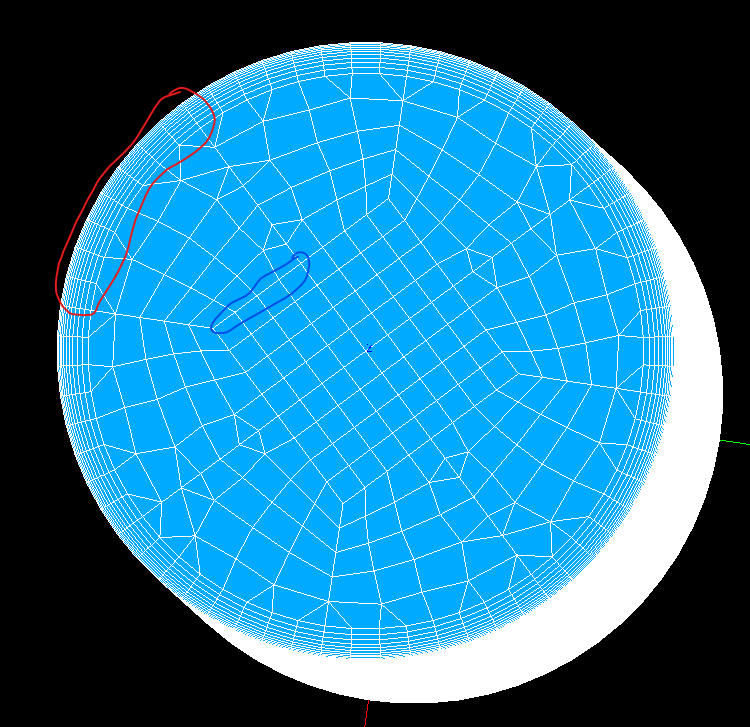
When I generate the mesh, I get the errors which one can see running my file. But what worries me most of all is shown on the image below. The image is the screenshot of my mesh. Have a look at the red and blue circled regions. Normally, the amount of divisions (cells) in the red and blue circled regions must be the same (for instance, see the meshed pipe in this post). But I get more cells in the red regions.
I’m wondering how to make them the same.
I’m using Salome v9.9.0 on the latest Windows update.
can you instead upload the study (HDF file) such that experts can give some guideline? The attached python script triggers an error when I try to run it.
@NabilG, thanks, I uploaded the link to my .hdf file (please, see the redacted version of my post). The file is too big to upload it directly to this forum.
A note. I noticed people here share the .py versions of their files. I think that’s because .hdf files can be too big to share. That seems great but Salome doesn’t handle loading .py scripts very well. In your post - that I cited in my question - you share your .py script. But when I try to load it, I get an error. I decided I didn’t know how to properly load .py scripts and that experienced users know how to do that. But since you’re telling me that you, as well, get the error loading my script, I conclude that Salome doesn’t have a good implementation of script loading. So, maybe, it’s a good idea to address this issue in the next Salome update.
I did try going through the manual and this forum for the best practices loading somebody’s .py script. I didn’t find any.
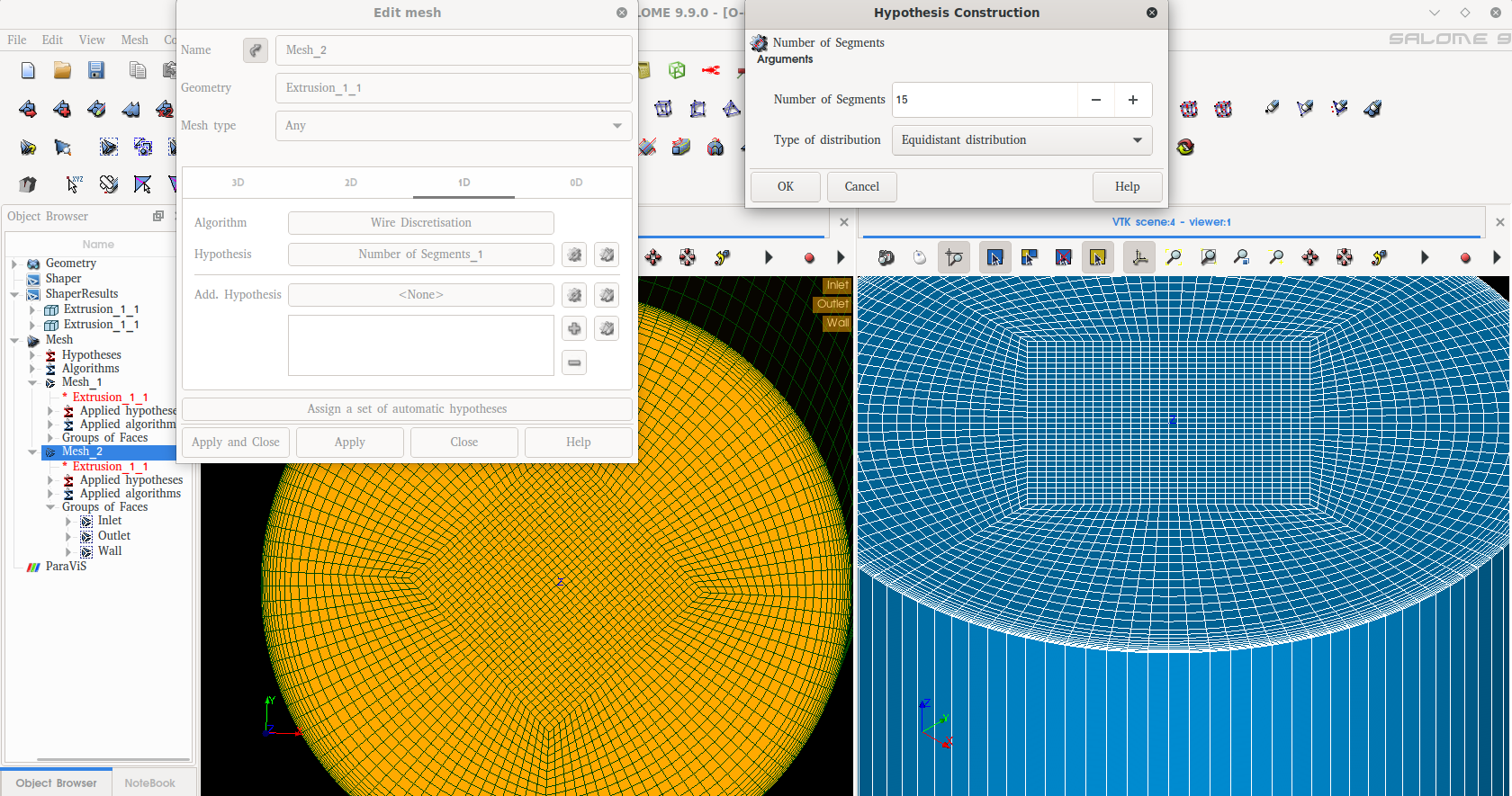
thanks for sharing the hdf study. the issue was discussed with experts. Here, you need to change the 1D hypothesis to “Number of segments”. Below a screen capture showing the resulting mesh.
I can swear I had tried “Number of segments” before to no luck. But it works now.
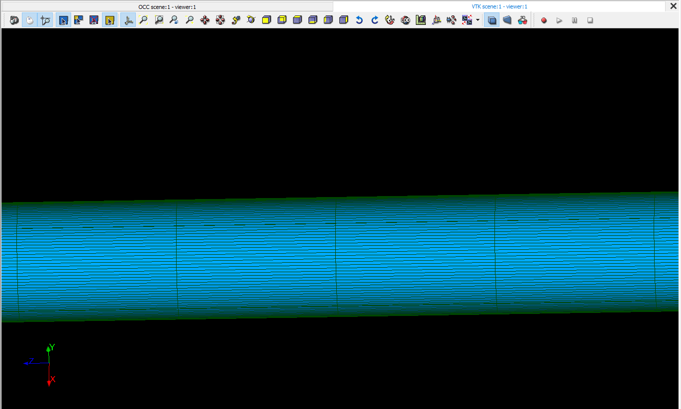
Even though it solves the problem, it gives rise to another problem. Please, see the attached screenshot: I have the fixed amount of segments. It is fixed within the cross section and along the axial direction of the pipe. The cross section is small and 15 segments give me a good resolution. But the pipe is long and the length of a segment is big. That might not be good for CFD simulations in certain situations. I’m going to play with the parameters to see if I can assign different number of segments along different 1D elements. Meanwhile, if you already know the solution to that problem, I’m wondering if you can share it please.
P.S. Here’s the explanation for newcomers like me why Nabil’s solution works. “Local length” assigns the length of an element along any of the edges. The outer circle has a greater length then the inner square. Therefore, the outer circle can have more cells of the same length than the inner square. That is why I would get more cells in the red circled region than in the blue circled region (see the image in my question). On the other hand, “Number of segments” specifies the fixed number of cells along any edge. That is why it gives me the same number of cells in the red and blue circled regions.
That works, thank you so very much @NabilG !
Rarely I get such a good quality help on a forum. I do appreciate your help!
In case the .hdf files are lost, here’s the brief guide for newcomers on how to do the O-grid mesh.
In Shaper’s sketch mode, draw a circle with the inner blocks in it like it is shown in this tutorial.
1a) Make sure, one of the radial lines starts on one of the axes. For details see this tutorial (starting the 9th minute). Actually in this post, Nabil mentions there is an extra edge removing option in Geometry module. I, personally, tried it and it didn’t work for me (may be I was doing something wrong). So, I adhered to Cyprien’s solution.
Extrude the sketch.
Create groups: Inlet, Outlet, Wall, Axial direction. For details, see this tutorial (starting 11:17min). Inlet, Outlet, Wall are the surface groups. Axial direction is the line group - the one that Nabil talks about when he is suggesting the solution to making more divisions in the axial direction.
Click on the Mesh module.
To assign mesh conditions, follow either one of Cyprien’s tutorials that I have referenced.
5a) First, create a mesh for the extrusion (pick the extrusion for the geometry in 3D tab). 3D algorithm: Hexahedron (i,j,k), 3D hypothesis: Default, 3D Add. hypothesis: Viscous layers (add Inlet and Outlet to the Faces without layers - see the second Cyprien’s tutorial). 2D algorithm: Quadrangle:Mapping, 2D hypothesis: Quadrangle Parameters (pick Standard), 2D Add. hypothesis: None. 1D algorithm: Wire discretization, 1D hypothesis: Number of segments (see the first Nabil’s solution). Don’t do anything in 0D tab.
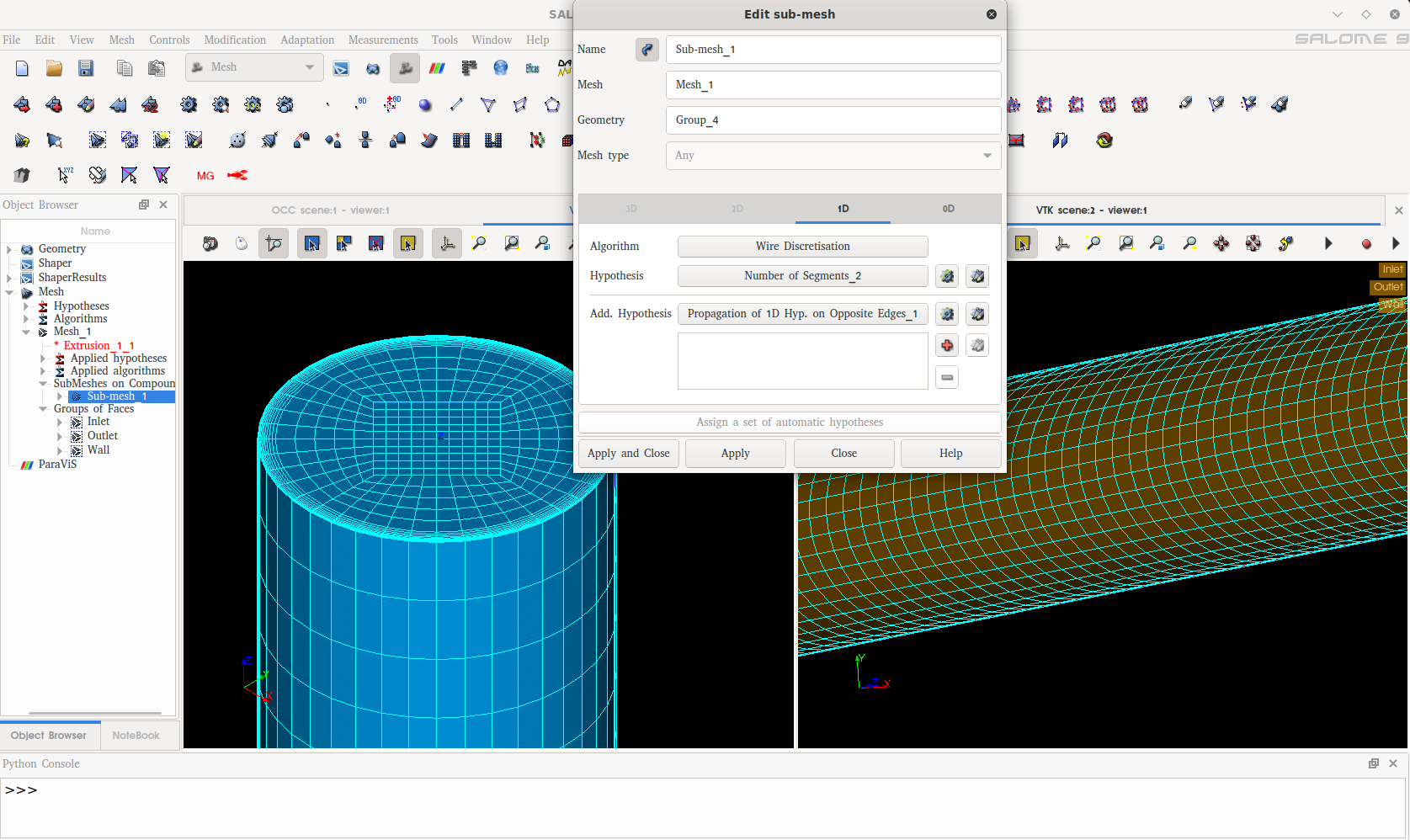
5b) You’ll see the name of your mesh in the tree (if you used default name, it is Mesh_1). Right click on it → Create Sub-mesh. Create it for Axial direction group as Nabil described in his second solution.